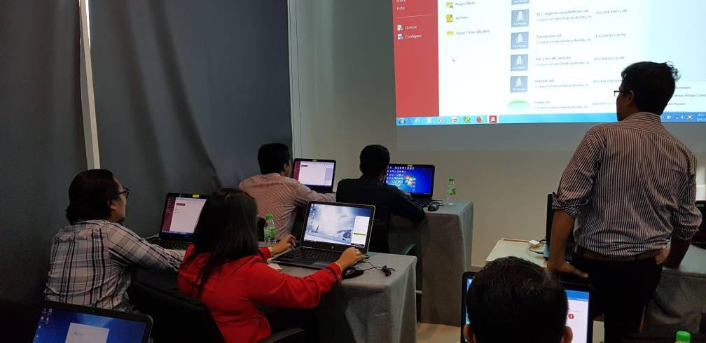
Cype Software is launching a SERIES of Webinars on our BIM compliant solutions for both Structures and MEP.
We are also introducing 2 new applications which we are offering for free
CYPE has developed innovative solutions for over the last 30 years
Other than Bentley solutions we have introduced CYPE to Malaysia which has many advantages over Bentley.
CYPE developed over the last 30 years solutions for structures and MEP.
Cype has been providing CAD / BIM software solutions for three decades and we support more than 100,000 customers in 60 countries around the world and collaborate with more than 500 universities that incorporate our software in their academic and research functions. OpenBIM Systems has been developed for Fujitsu, Midea, Toshiba, S&P, Saint-Gobain etc.
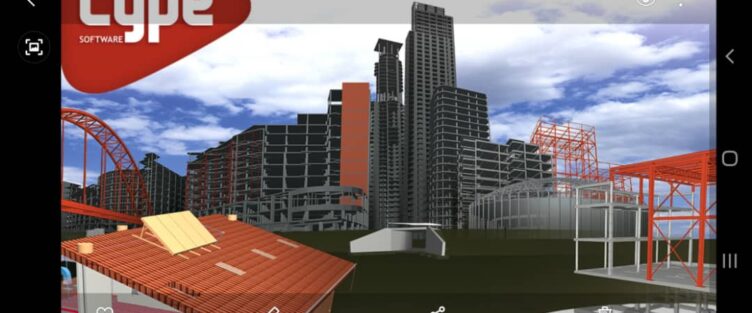
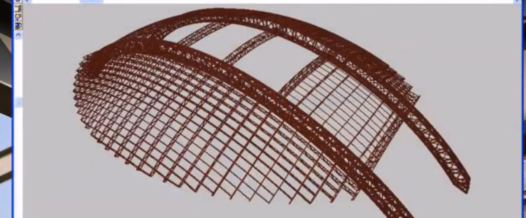
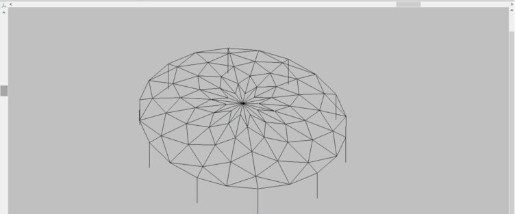
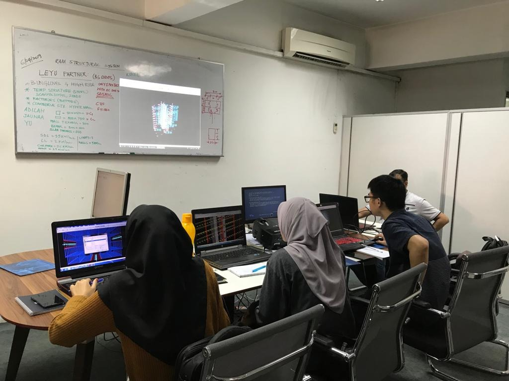
This is the very old version of Cype.
the reason we uploaded it here is this software could do many type of structures and now it has more power and ability in the version of 2020.
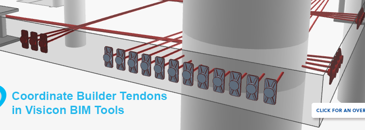
Visicion Model Review and Validation – Provides a unified BIM model review and validation solution for ADAPT, Revit, ETABS and IFC (Tekla) projects. Use it to view, markup, measure, and validate model data using a simple-to-use interface. Learn one solution to interact with all of your BIM models. Reads ADAPT-Builder model data and creates detailed 3D BIM tendon data that can be used for constructability checks and project coordination
Visicon BIM:
Smarter 3D model review and validation
Review, merge, measure and validate your BIM models
CYPECAD was brought about to carry out the analysis and design of reinforced concrete and steel structures, subject to horizontal and vertical forces, for houses, buildings and civil work projects.
IDEA StatiCa partners with Hilti to advance anchor design technology
Hilti Group and IDEA StatiCa s.r.o. have entered into a software development agreement focusing on a component-based, finite element method (CBFEM) for anchoring/footing topologies to help improve workflow efficiency.
Hilti and IDEA StatiCa have entered into an agreement to further improve the speed and accuracy of steel-to-concrete connection analysis for structural engineers. With this development, Hilti and IDEA StatiCa strengthen seamless workflows and increase productivity and safety in construction projects.
The new software solutions will support structural engineers with advanced base plate design, weld, and stiffener design and finite element analysis.
Oliver Glockner, Head of Application Software Product Management at Hilti said, “We see that connections and anchoring, as well as workflows, are getting more and more complex. We support structural engineers with the latest analysis technology to further help them improve their speed, accuracy, and processes.”
New solution launched
To solve today’s/future challenges, a fundamentally new approach to steel-to-concrete connection analysis was needed. With Hilti’s knowledge in anchors and concrete and 10+ years of construction software experience combined with IDEA StatiCa’s knowledge in steel design and FEM, a unique solution for these problems has been developed.
The new approach is based on a robust finite-element solver with accurate material models as well as a unique description of the anchor behavior to allow a realistic design of the full connection. In addition, the two companies have been working together to solve challenges in the current design process such as multiple, manual data transfers; design assumptions that don’t fit together, such as rigid and non-rigid baseplate; and improving the management efficiency of changes across the workflow.
Early involvement and feedback of customers supported the improvements:
Marianne Johannsson, Structural Engineering Manager at Balco Group, said “Design of a plate (full connection including anchors, stiffeners, base plate, etc.) might take up to 4 hours plus 2 hours to create the report. PROFIS Engineering Suite could save us up to 50% of the time. We’ve been waiting for this!”
Per Jørstad, Structural Engineer at Sweco, said, “We can save up to 50% in time spent – from 2-6 hours to 1-2 hours – by doing all checks with one piece of software.”
“We believe that the new component-based finite element method (CBFEM) is the right approach to break the limits of anchoring/footing topologies while keeping safety first. We put the CBFEM into the core of our product, IDEA StatiCa Connection, and Hilti has integrated it in their new PROFIS Engineering Suite”, said Lubomir Šabatka, CEO at IDEA StatiCa.
Webinar Hilti & IDEA StatiCa: Safety & efficiency in steel-to-concrete connections
import DXF and DWG files to Cype3D for Structural and Analysis and Designs
CYPE 3D is an agile and efficient program brought about to carry out structural calculations in 3 dimensions of bars made up of steel, timber, aluminum, concrete or any other material, including the foundations with pad footings, piles and strap and tie beams. If the structure consists of timber, steel or aluminum bars, the program can redesign them and so obtain their maximum optimisation.
CYPE 3D Power, efficiency and productivity for steel, timber, aluminium and concrete structures
It is an agile and efficient program brought about to carry out the design of three dimensional structures composed of steel and timber bars, and their foundations, which includes pad footings, pile caps and strap and tie beams. Additionally, these can be redesigned and so obtain their maximum optimisation.
It has been adapted to national and international steel, timber, aluminium and concrete construction codes. The program carries out the analysis, design and check of the fire resistance of timber sections. Performs a seismic analysis of the structure (Modal Spectral Analysis) according to national and international codes. Second order effects (P-delta) are considered with wind and seismic loads.
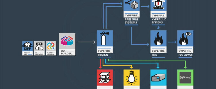
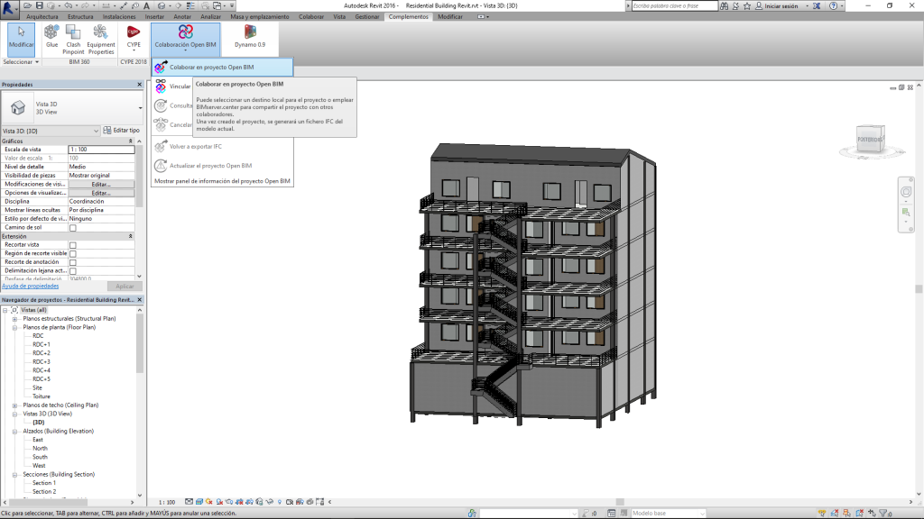
BIMserver.center is the cloud storage platform from which to create, manage and share all our BIM projects. Its versatility allows you to start working from IFC Builder, Open BIM Plugin – Revit, IFC Uploader or CYPECAD MEP.
CYPEFIRE Design is designed to assist the designer in the process of designing and verifying the characteristics of the building and fire protection facilities.
The evacuation of occupants, the compartmentalization of the sectors and the accessibility of firefighters are some of the many checks that are carried out in the application.
It also serves as a starting point for the workflow, since from here requirements for the structure’s fire resistance, sprinkler installation, etc. are included.
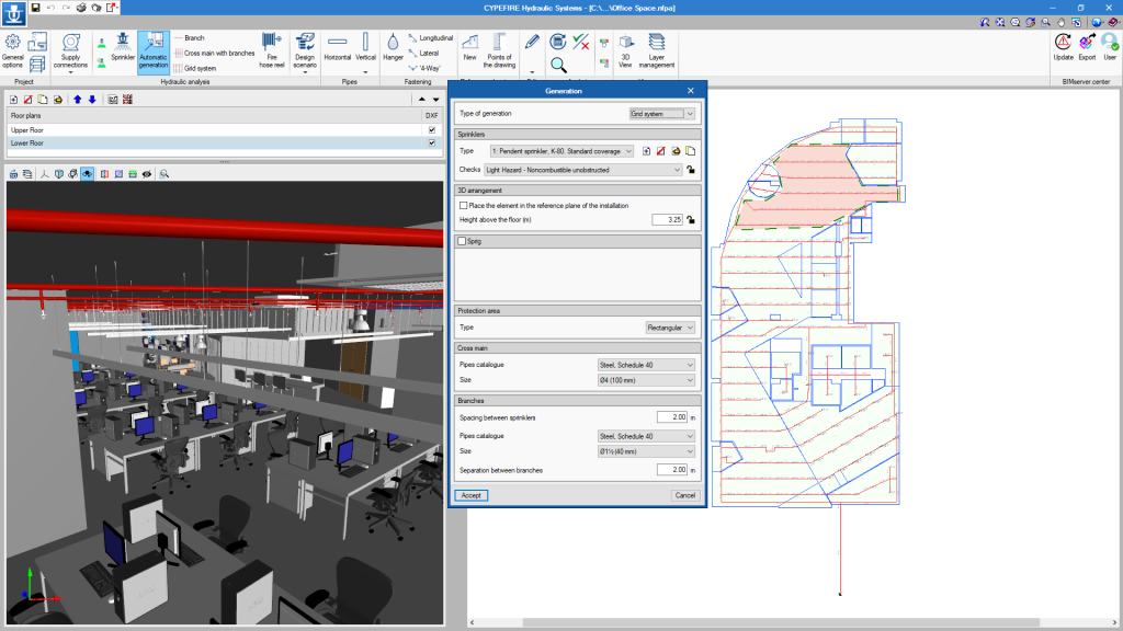
CYPEFIRE Hydraulic Systems
CYPEFIRE Hydraulic Systems work interface
The requirement generation by CYPEFIRE Design of the sprinkler installation allows users who begin this phase of the project to know where the design is necessary.
CYPEFIRE Hydraulic Systems allows calculation and design of fire networks according to NFPA 13, EN 12845: 2016 and CP 52: 2004 regulations. The information provided to the BIM model on sprinkler arrangement will be of great help when we decide to perform the dynamic fire simulation.
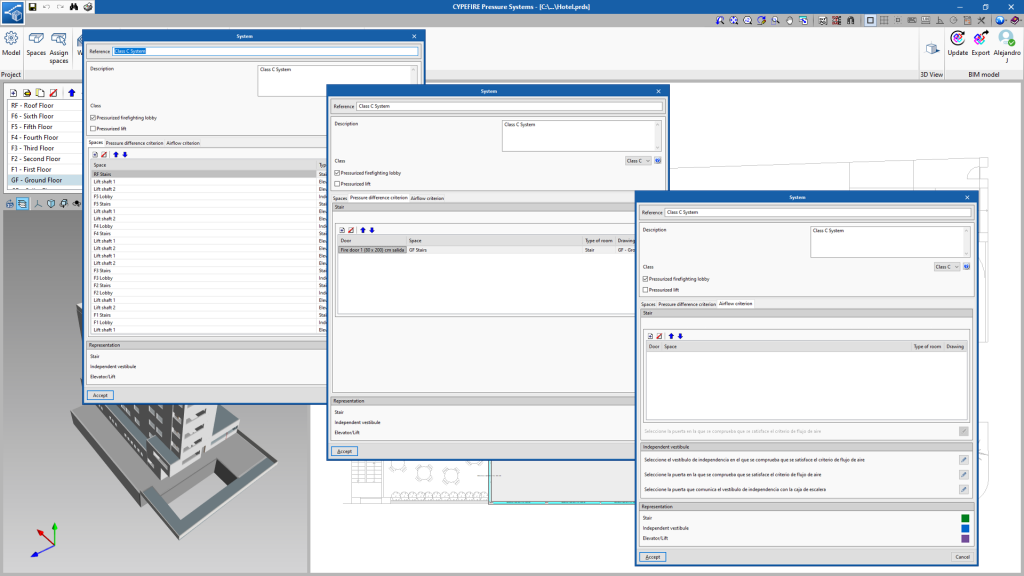
CYPEFIRE Pressure Systems
Assistant for the definition of a pressurization system
Fire smoke control is a fundamental part of being able to safely evacuate all occupants of the building.
To meet this need, CYPEFIRE Pressure Systems was born, an application for the design of staircase overpressure systems according to EN 12101-6.
The communication with the BIM model allows us to know which stairs require installation of this type. Also, the export of the calculation results allows dynamic simulation of the pressurized compartments.
CYPEFIRE FDS
Fire simulation in the parking lot of a residential building
Dynamic fire simulation is one of the most complex parts when designing a fire prevention project.
Thanks to all the information that has been included in the BIM project in the previous steps, we start with a great advantage since CYPEFIRE FDS is able to integrate the information of the BIM model, so that performing a simulation has never been so simple.
In addition to the workflow we also have CYPEFIRE FDS Viewer so that all project participants can view the results.
This is the end of the main workflow in the field of fire protection. But this Use Case does not end here, as there are many other applications whose use by designers is necessary to complete the final project.
Complementary Applications
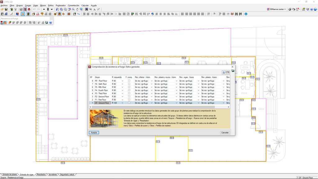
CYPECAD
Structure fire resistance calculation
One of the best applications for the calculation and sizing of reinforced concrete structures and metal structures, CYPECAD also collaborates in the design phase of the fire project.
From CYPEFIRE Design, the information generated from the fire sectors and special risk premises is exported so that, comfortably, on the CYPECAD interface we have all the fire resistance requirements of the structure to be checked.
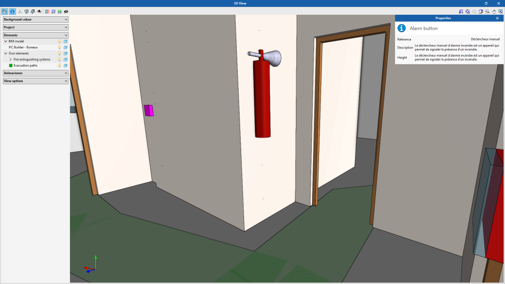
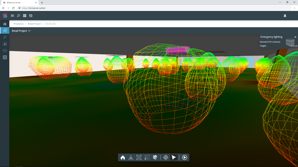
CYPELUX
Visualization of photometric curves in BIMserver.center
For the calculation of emergency lighting and evacuation means we have CYPELUX.
This free application allows the reading of fire fighting equipment (fire extinguishers, fire hydrants, alarm buttons) and the evacuation routes introduced in the project to perform the minimum lighting check.
The software is also parameterized, so we can easily modify the calculation criteria to adapt them to the regulations we want to comply with.
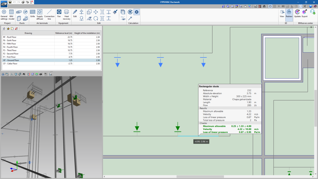
CYPEHVAC Ductwork
Calculation of the load losses produced in the ducts
The calculation and dimensioning of the duct networks that we carry out with CYPEHVAC Ductwork can be used to calculate the smoke control systems, for example, that are required to protect parking lots.
Through the simple interface, you can arrange all the air intake grilles and design the passage of the ducts, in order to obtain the necessary flow to meet the required fire protection conditions.
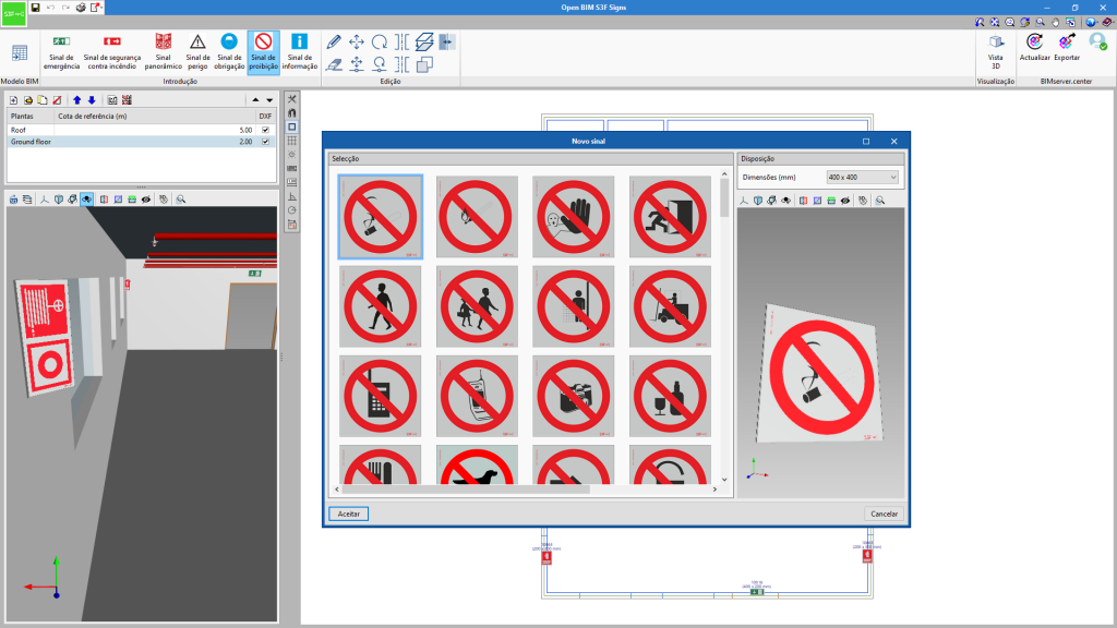
Open BIM S3F Signs
Signal introduction in Open BIM S3F Signs
For the final phases of the project, we have Open BIM S3F Signs, an application for the installation of signage according to the catalogues of the manufacturer S3F Signs.
The great versatility of the program allows users to read all the signals introduced in the fire protection or accessibility project, as well as to select any sign from catalogues, from countries such as Portugal, Spain, United Kingdom and France.
Graduado en Ingeniería Mecánica y especializado en el diseño de Protección Contra Incendios. Amante del fútbol sala y la NBA, le encanta disfrutar de su tiempo libre con los más cercanos.
Presentation IDEA StatiCA at Autodesk university in Las Vegas
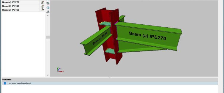
Application IDEA StatiCa Connection can design all types of welded or bolted connections, base plates, footing and anchoring. It provides precise checks, results of strength, stiffness and buckling analysis of a steel joint. Bolts, welds and concrete blocks are checked according to EN/AISC/CISC/AU/SP 16/ Chinese/ Russian. Templates for most-used connections are available as well as wide range of predefined hot rolled and sheet welded members.
IDEA StatiCa in the global workflow
Do your project from scratch or build on geometry and loading imported from Robot, Revit, MIDAS Civil + Gen, STAAD.Pro, SAP 2000, Scia Engineer, RFEM, RSTAB, AxisVM, ConSteel and others.
Take advantage of the link between IDEA StatiCa and Tekla Structures or Advance Steel to provide workshop drawings and support manufacturing process.
watch the Presentation IDEA StatiCA at Autodesk university in Las Vegas